
Grid vs. Solid Base Charge Trays: Optimizing Heat Distribution in Thermal Processing
If you've ever been responsible for a heat treatment operation, you know the feeling. You've got the furnace dialed in. The temperature profile looks right. The cycle time is where it should be. But when you pull the parts out, the results are inconsistent. Hardness varies across the batch. Case depth isn't uniform. And you're left wondering what went wrong.
I've sat through enough quality review meetings to know that the problem often isn't the furnace. It's the tray. More specifically, it's the choice between a grid tray and a solid base tray—and whether that choice matches what the process actually needs.
Let me walk you through the real differences between these two designs, what they mean for heat distribution, and how to make the right call for your thermal processing application.
What Are Charge Trays and Why Do They Matter?
A charge tray is a furnace fixture used to hold, support, and transport workpieces through high-temperature thermal processes like annealing, hardening, carburizing, nitriding, and tempering. They're not passive carriers—they're engineered components that directly affect thermal uniformity, atmospheric consistency, and part quality throughout the entire heat treatment cycle.
Here's what I've learned from working with these things. A tray that warps, oxidizes excessively, or conducts heat unevenly will produce inconsistent results even when the furnace itself is performing correctly. In a high-volume automotive heat treatment operation, a single batch of improperly supported gears can result in surface hardness variation of ±5 HRC or more—well outside acceptable tolerances. And more often than not, the culprit isn't the furnace parameters but the tray design.
Beyond part quality, charge trays represent a significant recurring cost. In continuous pusher and belt furnace operations, trays may complete thousands of thermal cycles per year. Selecting a tray design and alloy that extends service life from 200 cycles to 800 cycles can reduce annual fixture costs by 60% or more.
The fundamental distinction in charge tray design comes down to the base: grid (open) or solid. Each has its own heat distribution characteristics, load support capabilities, and application fit.
Grid Base Charge Trays: Design and Heat Distribution
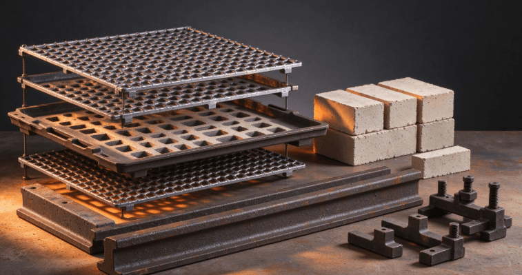
A grid base charge tray features an open structure with intersecting bars or cast grid patterns. The open configuration supports circulation around the loaded parts. The design priorities center on gas flow—raised feet, open grid patterns, and support post spacing allow hot gas to flow around all surfaces, enabling uniform heating from bottom to top.
How Grid Trays Distribute Heat
The open grid design allows furnace atmosphere—whether it's gas, air, or a controlled atmosphere—to circulate freely around the workpieces. This is critical in atmosphere furnace applications such as gas carburizing or gas nitriding. When hot gas can reach all surfaces of the parts, the heat transfer is more uniform and the chemical reactions (like carbon or nitrogen diffusion) happen more consistently.
Here's a concrete example. In a carburizing application, a solid-floor tray can create a "shadow" zone directly beneath stacked parts, resulting in lower carbon potential at the part surface closest to the tray floor. Switching to a mesh-floor design in the same application has been shown to reduce case depth variation by 15–25% across the batch.
When Grid Trays Excel
Grid trays are the preferred choice when atmosphere circulation is critical to the process. This includes:
Gas carburizing and nitriding: Where uniform gas exposure determines case depth consistency
High-volume production: Where throughput and cycle time matter
Parts with complex geometries: Where all surfaces need equal exposure to the furnace atmosphere
Applications requiring rapid heating and cooling: Where the open design reduces thermal mass
A typical charge tray from a heat-resistant steel foundry operates in the 800–1100°C range, with reference diameters from ∅1200 to ∅3600 mm and single-piece weights from 300 to 8000 kg. Grid patterns can be cast into the tray during the casting process, eliminating weld joints that can become failure points under thermal cycling.
Solid Base Charge Trays: Design and Heat Distribution
A solid base charge tray features a continuous, uninterrupted floor surface. The design priorities are different: maximum part support, stability, and protection for small or delicate components.
How Solid Trays Distribute Heat
A solid tray conducts heat primarily through the metal itself rather than through convection from the furnace atmosphere. The solid floor acts as a thermal mass—it absorbs heat and radiates it upward to the parts resting on it.
This can be an advantage in some applications. The solid base provides a stable, flat surface that supports parts evenly. It prevents small components from falling through gaps and maintains consistent part orientation.
But there's a trade-off. The solid floor blocks gas flow. Parts stacked too densely, with airflow blocked by solid tray floors, can experience inconsistent heating. The areas of parts in direct contact with the tray floor may heat differently than the exposed surfaces. This is the "shadow" effect mentioned earlier—and it's a real problem in atmosphere-controlled processes.
When Solid Trays Excel
Solid base trays are the better choice when:
Parts are small or delicate: Where they might fall through grid openings
Maximum support is required: For heavy, irregularly shaped parts
Parts must maintain precise orientation: Where movement during the cycle is unacceptable
Simple heating or tempering applications: Where atmosphere circulation is less critical
Solid-floor heat treatment trays provide maximum part support and are best for small or delicate components. They're also commonly used in pit furnace applications where vertical stacking requires a stable base.
Direct Comparison: Grid vs. Solid Base
Let me put this side by side so you can see the differences clearly.
Feature | Grid Base Charge Tray | Solid Base Charge Tray |
Gas circulation | Excellent—open pattern allows free flow | Poor—solid floor blocks gas movement |
Heat distribution | Uniform through convection | Can create "shadow" zones beneath parts |
Part support | Limited to grid contact points | Full, continuous support surface |
Small parts | May fall through gaps | Securely supported |
Case depth consistency | Superior in carburizing/nitriding | May show 15-25% variation in shadow zones |
Thermal mass | Lower—heats and cools faster | Higher—slower response, more stored heat |
Atmosphere furnace suitability | Preferred | Limited |
Vacuum furnace suitability | Excellent | Can be used but gas flow is restricted |
Typical operating range | 800–1100°C | 800–1100°C |
Typical size range | ∅1200–∅3600 mm | ∅1200–∅3600 mm |
Single-piece weight | 300–8000 kg | 300–8000 kg |
The open grid design supports circulation around the loaded parts. Raised feet on the base tray and open grid patterns allow hot gas to flow around all surfaces. This is the key advantage of grid trays in atmosphere-controlled processes.
Material Selection for Charge Trays
Material selection is where the design choices meet the operating reality. The operating range for heat-resistant steel charge trays is typically 800–1100°C, but the specific alloy choice depends on the temperature, atmosphere, and cycle requirements.
Common Alloy Families
HH alloy (25Cr-12Ni): Suited for temperatures up to 1090°C. Good oxidation resistance and moderate cost. Widely used in carburizing and neutral hardening applications.
HK alloy (25Cr-20Ni): Higher nickel content improves creep resistance at elevated temperatures. Preferred for longer cycle times and heavier loads.
HT alloy (15Cr-35Ni): Excellent resistance to thermal fatigue. Commonly used in carburizing atmosphere applications where carbon pickup by the tray itself must be minimized.
HP alloy (25Cr-35Ni + Nb): Niobium additions improve strength at very high temperatures. Used in demanding gas carburizing and vacuum heat treatment applications up to 1150°C.
Ni-base superalloys: Reserved for the most extreme temperature applications above 1100°C where iron-base alloys approach their service limits.
Cast vs. Fabricated Construction
For high-temperature, high-cycle applications, cast construction is generally preferred over fabricated (welded) construction. Cast trays have no weld joints that can fail under thermal cycling. A drawing-based cast charge tray developed around the customer drawing, load pattern, operating temperature, and handling requirements offers better reliability in demanding furnace environments.
Application-Specific Recommendations
Let me give you some practical guidance based on what I've seen work in the field.
For Gas Carburizing and Nitriding
Choose grid base. The open design allows the carburizing or nitriding atmosphere to reach all surfaces of the parts. This is non-negotiable if you need consistent case depth. As the data shows, switching to a mesh-floor design can reduce case depth variation by 15–25%.
For Small or Delicate Parts
Choose solid base. Small components will fall through grid openings. You need the continuous support surface. Just be aware of the thermal shadow effect and adjust your process parameters accordingly.
For Vacuum Heat Treatment
Either can work, but grid trays are often preferred. In vacuum furnaces, radiative heat transfer is the primary mechanism, and the open grid allows more uniform radiation exposure. However, the specific tray geometry must be adapted to the furnace and load conditions.
For Heavy, Irregular Parts
Solid base is often the practical choice. The full support surface distributes the load evenly and prevents point-loading that can deform the tray or the parts.
For Continuous Furnace Operations
Grid trays often win on throughput. Lower thermal mass means faster heating and cooling cycles. In high-volume production, those seconds per cycle add up.
Real-World Application: Automotive Gear Heat Treatment
Let me share an example that illustrates the practical difference between these two designs.
An automotive transmission manufacturer was running a gas carburizing operation for helical gears. They were using solid-floor cast trays. The process spec called for case depth of 0.8–1.2 mm with surface hardness of 58–62 HRC.
The problem was inconsistency. Some gears came out at the high end of the case depth range; others came out at the low end. Surface hardness varied by ±4 HRC across the batch. The quality team spent months tweaking furnace parameters—temperature, cycle time, carbon potential—with limited improvement.
The real issue wasn't the furnace. It was the tray. The solid floor was blocking gas circulation beneath the stacked gears. The gears in the center of the stack—closest to the tray floor—were seeing lower carbon potential than the gears on top.
The plant switched to a grid-floor cast tray with the same outer dimensions. The open grid pattern allowed the carburizing atmosphere to reach all surfaces of every gear. Case depth variation dropped from ±0.25 mm to ±0.08 mm. Surface hardness variation dropped to ±1 HRC. The scrap rate fell by 60%.
The grid tray cost about 15% more than the solid tray. But the reduction in scrap and rework paid for the upgrade in less than three months.
What's the lesson? The right tray design isn't about which one is "better" in the abstract. It's about which one fits the process.
Frequently Asked Questions
What's the main difference between grid and solid base charge trays?
Grid base trays have an open structure that allows furnace atmosphere to circulate freely around the parts. Solid base trays have a continuous floor that blocks gas flow but provides maximum part support.
Which type provides better heat distribution?
Grid trays generally provide more uniform heat distribution in atmosphere-controlled processes because the open design allows hot gas to reach all surfaces. Solid trays can create "shadow" zones where gas circulation is blocked.
When should I choose a solid base tray?
Choose solid base when you're processing small or delicate parts that might fall through grid openings, when you need maximum part support, or when the process doesn't require atmosphere circulation.
When should I choose a grid tray?
Choose grid when you're running gas carburizing, nitriding, or any atmosphere-controlled process where uniform gas exposure is critical. Grid trays are also preferred in vacuum furnaces and high-volume production where faster thermal response matters.
What materials are charge trays made from?
Heat-resistant alloy steels are the most common, including HH (25Cr-12Ni), HK (25Cr-20Ni), HT (15Cr-35Ni), and HP (25Cr-35Ni + Nb) alloys. Nickel-base superalloys are used for extreme temperatures above 1100°C.
What's the typical operating temperature for charge trays?
The typical operating range is 800–1100°C, with some premium alloys capable of continuous operation up to 1150°C.
Can grid trays support heavy loads?
Yes. Cast grid trays are engineered with reinforced structures to support heavy loads. Typical single-piece weights range from 300 to 8000 kg.
Final Thoughts
Look, I've been around enough heat treatment operations to know that charge tray selection often gets treated as an afterthought. "Just get something that fits the furnace" is something I hear all the time. And that's a mistake.
The choice between a grid tray and a solid base tray isn't cosmetic. It directly affects heat distribution, case depth consistency, cycle time, and—ultimately—part quality. In gas carburizing applications, switching from solid to grid can reduce case depth variation by 15-25%. That's not a small number. That's the difference between parts that pass inspection and parts that go to the scrap bin.
Start with the process requirements. If atmosphere circulation is critical—carburizing, nitriding, or any controlled atmosphere process—grid is almost always the right call. If you're processing small parts that need full support, solid base is the practical choice.
Then look at the material. HH alloy for moderate temperatures and cost sensitivity. HK for heavier loads and longer cycles. HT for thermal fatigue resistance in carburizing atmospheres. HP for demanding high-temperature applications.
And for heaven's sake, don't try to save money by buying a generic tray and hoping it works. A drawing-based cast charge tray developed around your specific furnace, load pattern, operating temperature, and handling requirements will deliver better results and lower total cost of ownership than an off-the-shelf compromise.
The numbers don't lie. The right tray design reduces scrap. It improves consistency. It extends service life. Choose wisely.